
Crankcase Level Switches
The FW Murphy L971 Series Level Switch detects low oil level in a compressor’s crankcase.
- Durable low level switch
- Replaces non explosion-proof switch on Ingersoll-Rand compressors
- Adaptable to other compressors
- Installs with minimal downtime
FW Murphy Production Controls offers support for all our products. If you are unable to find the product that you need, please call us at 918-957-1000.
As oil level in the crankcase depletes, the float on the L971 switch falls, and when reaching the predetermined limit, it will trip the internal snap-switch sounding an alarm or initiating shutdown.
The L971 is designed for Ingersoll-Rand Type 30, Type 40 and ESH compressors, yet it can be adapted to fit other compressors that have an inspection plate extending below normal operating oil level. It installs with minimal downtime and has a two-year limited warranty.
The L971 has a 1/2 NPT process connection and features an explosion-proof enclosure, durable SPDT snap-switch and rigid polyurethane foam float. A 304 stainless steel float is available on certain configurations.
- Operating Temperature Range: -15 to 275°F (-26 to 135°C)
- Maximum Working Pressure: 30 psi (206 kPa) [2.06 bar]
- Switch Rating: 4 A @ 250 VAC
- Case: Aluminum (explosion-proof)
- Mounting Adaptor: Brass
- Floats: Rigid polyurethane. 304 stainless steel available on L971-C only
- Other Wetted Parts: 303, 304 and 316 stainless steel
- O-Ring Seals: Viton and Buna
- Process Connection: 1/2 NPT
- Hazardous Location Rating: UL and CSA listed for Class I, Groups C & D; Class II, Groups F & G
- Enclosure Type / Ingress Protection Rating: IP66 per IEC 60529
- Conduit Connection: 1/2 NPT
- Wire: 18 AWG (0.75 mm2)
- Shipping Weight: 1 lb. 10 oz. (0.7 kg)
- Shipping Dimensions: 8-1/4 x 4-1/4 x 4-1/2 in. (210 x 108 x 114 mm)
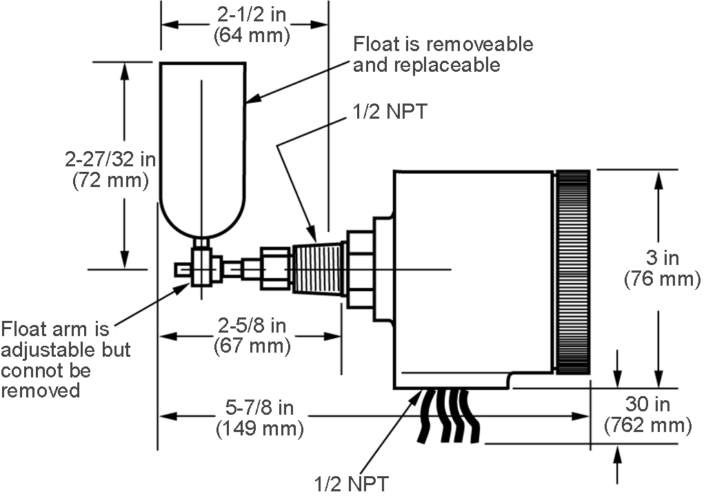
Dimensions L971
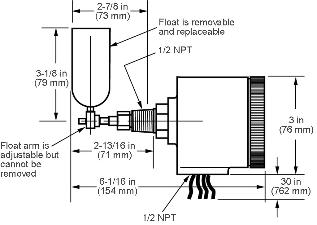
Dimensions L971-C
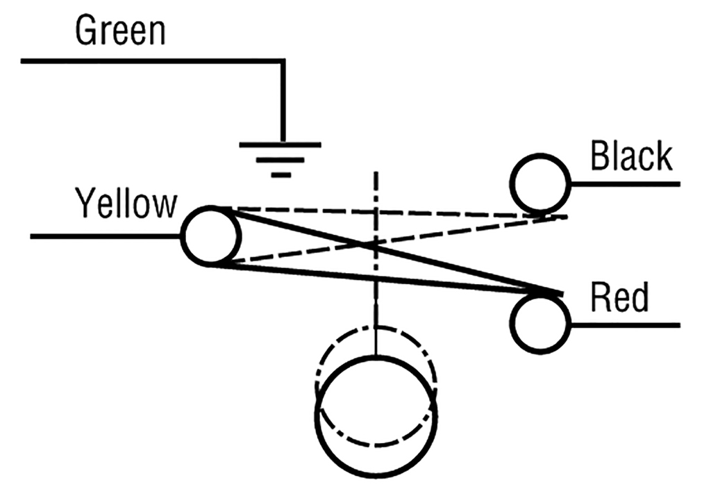
Wiring L971 and L971-C
Diagram is shown in the shelf position with no force acting upon float.
For more information about this product, you can download the related literature here: