
This Quality Alert covers FW Murphy LS200, LS200 D and LS200 SS Liquid Level Switch products manufactured from November 2024 to March 2025. If you are receiving this Quality Alert, you should check your parts and stock to determine whether you have any in-scope products.
FW Murphy has identified a potential issue present in a small percentage of units that could result in a state of constant actuation. Under certain circumstances, this condition could result in the microswitch not activating, even when the float moves. Depending on the specific application, this condition could result in a potential hazard. Again, not every in-scope product is impacted by this potential issue.
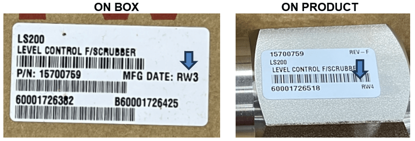
LS200, LS200 D, and LS200 SS Liquid Level Switches produced and shipped between November 2024 and March 2025 can be identified by date codes printed on the white sticker located either outside the box or on the exterior of the product, as shown in the images below. The date code is visible on the right side of the white sticker, indicated by the blue arrows in the images below. If the manufacturing date code is RV11, RV12, RW1, RW2 or RW3, this Quality Alert applies to the product. If the manufacturing date code is not one of the above, the product is not impacted but can be checked as a precaution.
If your product shows manufacturing date code RV11, RV12, RW1, RW2 or RW3, please immediately proceed with the following two options:
If you choose to inspect the product, please follow the inspection instructions below.
The estimated inspection time is two minutes per product. If the potential issue exhibits itself as described below, discontinue use of that liquid level switch and contact FWMWarranty@doverprecision.com for an RMA. If your inspection reveals no issue, you may continue to use the product
Inspection Instructions
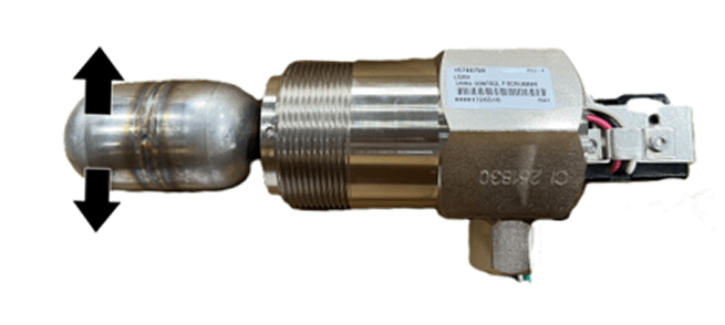
Conversely, attaching the multimeter’s RED probe to the BLACK wire on the LS200 unit, and the BLACK probe on the meter to the WHITE wire on the LS200 will be another check of functionality. No continuity will be present when the switch is active (float up state); however, when the float is moved to the resting position, the unit will present continuity.
NOTE: Depressing the arm that protrudes from the black microswitch DOES NOT ENSURE proper operation. Perform the tests as shown above to properly test the unit.
If you would prefer that FW Murphy inspect the product on your behalf, please contact FWMWarranty@doverprecision.com for an RMA. FW Murphy will either replace or repair the switch for you as soon as possible.
We value your business and regret any inconvenience caused by this Quality Alert. If you have any questions or concerns about this matter, please contact FWMWarranty@doverprecision.com.
Thank you,
Cody J. Toppel
Manager, Customer Quality
T: +1 281-633-4547 | M: +1 832-612-0021
ctoppel@doverprecision.com