
Liquid Level Swichgage®
The L150 Series Level Swichgage instrument is a combination liquid level gauge and low-limit switch; each unit includes (1) a chamber with pivotal float, (2) an indicating dial with pointer and (3) a low-level contact.
- Monitors level of coolant, lube oil, diesel fuel or hydraulic fluid
- Indicating gauge
- Low limit switch
- Float operated
- Explosion-proof model available
FW Murphy Production Controls offers support for all our products. If you are unable to find the product that you need, please call us at 918-957-1000.
The L150 Series Level Swichgage instrument is a combination liquid level gauge and low-limit switch; each unit includes (1) a chamber with pivotal float, (2) an indicating dial with pointer and (3) a low-level contact. When properly installed and maintained, the float operates the pointer which, in turn, both indicates level during normal operation and closes a switching circuit if the level falls to the low-limit set point.
Applications
The primary use of the L150/EL150K1 is for engine cooling systems, surge or expansion tanks, condenser radiator or vapor phase systems, pressurized or atmospheric systems. The Level Swichgage instrument can also be used to monitor lube oil, hydraulic fluid or diesel fuel reservoirs and activates alarms and/or shutdown at a predetermined minimum level. These instruments are built for low pressure systems with a maximum of 25 psi (172 kPa) [1.72 bar].
L150
- Maximum Temperature: 250° F (121° C)
- Maximum Operating Pressure: 25 PSI (172 kPa)
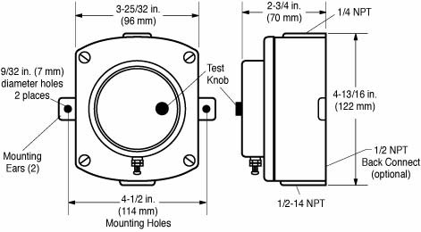
- Case: Die cast aluminum, polyurethane coated; approximate dimensions; 4-1/2 x 4-3/4 x 2-3/4 in. (114 x 121 x 70 mm)
- Mounting Holes: (2) 9/32 in. (7 mm) diameter at 4-1/2 in. (114 mm) on center
- Float: Brass
- Lens: Polycarbonate
- O-rings: Saturated Nitrile, suitable for coolant or hydrocarbons
- Gasket: Nitrile
- Vent Tube: 1/4 x 5 in. (6 x 127 mm) copper cane with 1/4 NPT x 1/4 in. (6 mm) tube fitting
- Contact Rating: 2 A @ 30 VAC/DC. Wire: (1) 16 AWG x 26 in. (1.5 mm 2 x 660 mm) with terminals
- Shipping Weight: 29 oz. (0.82 kg.)
- Shipping Dimensions: 5-1/4 x 5-1/4 x 5-1/2 in. (133 x 133 x 140 mm)
EL150K1
- Maximum Temperature: 250° F (121° C)
- Maximum Operating Pressure: 25 PSI (172 kPa)
- Case: Die cast aluminum, polyurethane coated; approximate dimensions; 5 x 4-3/4 x 2-3/4 in. (127 x 121 x 70 mm)
- Enclosure Rating: IP35
- Mounting Holes: (2) 9/32 in. (7 mm) diameter at 4-1/2 in. (114 mm) on center
- Float: Brass
- Lens: Polycarbonate
- O-rings: Saturated Nitrile, suitable for coolant or hydrocarbons
- Gasket: Nitrile
- Vent Tube: 1/4 x 5 in. (6 x 127 mm) copper cane with 1/4 NPT x 1/4 in. (6 mm) tube fitting
- Snap-Switch: SPDT rated 10 A @ 125 VAC; 0.5 A @ 125 VDC; 10 A 30 VDC
- Wire: (3) 18 AWG x 14 in. (1 mm 2 x 356 mm)
- Shipping Weight: 42 oz. (1.2 kg.).
- Shipping Dimensions: 5-1/4 x 5-1/4 x 5-1/2 in. (133 x 133 x 140 mm)
EL150EX
- Maximum Temperature: 250° F (121° C)
- Maximum Operating Pressure: 25 PSI (172 kPa)
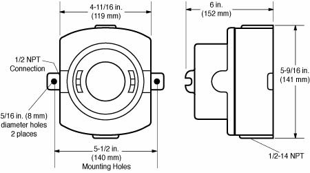
- Case: Sand cast aluminum, painted; approximate dimensions: 6-1/2 x 5-3/4 x 5-1/4 in. (165 x 146 x133 mm)
- Mounting Holes: (2) 5/16 in. (8 mm) diameter at 5-1/2 in. (140 mm) on center
- Float: 304 stainless steel
- Lens: Tempered glass
- O-rings: Saturated Nitrile, suitable for coolant or hydrocarbons
- Gasket: Nitrile
- Vent Tube: 1/4 x 5 in. (6 x 127 mm) copper cane with 1/4 NPT x 1/4 in. (6 mm) tube fitting and 1/2 NPT to 1/4 NPT reducer fitting
- Snap-Switch: SPDT rated 10 A @ 125 VAC; 0.5 A @ 125 VDC; 10 A 30 VDC
- Wire: Wired to terminal block
- Laboratory Approvals: CSA Listed for Hazardous Locations Class I, Division 1, Groups C & D
- Shipping Weight: 5 lbs. (2.26 kg.)
- Shipping Dimensions: 6-1/2 x 6-3/4 x 6-3/8 in. (165 x 171 x 162 mm)
Dimensions L150
Dimensions EL150K1

Dimensions EL150EX
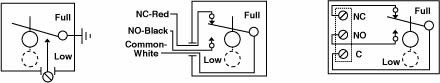
Standard Electrical Diagrams
For more information about this product, you can download the related literature here:
Sales Bulletin (00072; revision date: 02/2025)
Installation Instructions (00-02-0171; revision date: 3/2014)